
GB0-371-ENU Exam Question 36
The switches SWA and SWB are connected together through two optical fiber Gigabit Ethernet links, and the switch SWA has the following interface configuration:
[SWA]interface GigabitEthernet 1/0/1
[SWA-GigabitEthernet1/0/1]gvrp
[SWA-GigabitEthernet1/0/1]port link-type trunk
[SWA-GigabitEthernet1/0/1]port trunk permit vlan 1 10
[SWA]interface GigabitEthernet 1/0/2
[SWA-GigabitEthernet1/0/2]port link-type trunk
[SWA-GigabitEthernet1/0/2]port trunk permit vlan 1 10
If you want to configure link aggregation to aggregate these two links together, if the configuration on the SWB is correct, you can know from the above information
GB0-371-ENU Exam Question 37
In the network connection as shown in the figure, SWA and SWB enable STP and Loopback-detection at the same time. Please confirm that the port status description of SWA and SWB is correct.
GB0-371-ENU Exam Question 38
The customer LAN switches SWA, SWB, and SWC form the RRPP ring main ring 1, and the switch SWA has the following configuration information:
[SWA] rrpp domain 1
[SWA-rrpp-domain1] control-vlan 4092
k The above information can be known
[SWA] rrpp domain 1
[SWA-rrpp-domain1] control-vlan 4092
k The above information can be known
GB0-371-ENU Exam Question 39
In the switching network as shown in the figure, VLAN10 is set as Isolate-user-vlan on the switch SWA, VLAN2 and VLAN3 are the Secondary VLAN of VLAN 10; VLAN2? VLAN20 is created on the switch SWB, and VLAN20 is set as Isolate-user-vlan , VLAN4 is the Secondary VLA of VLAN20. After setting the IP address of each device as shown in the figure, you can judge
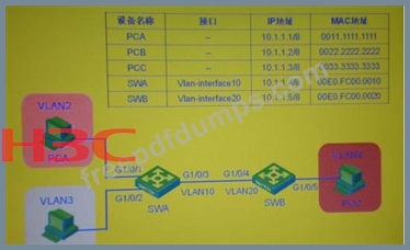
GB0-371-ENU Exam Question 40
In the switching network as shown in the figure, VLAN10 is set as Isolate-user-vlan on switch SWA, VLAN2 and VLAN3 are set as Secondary VLAN of VLAN 10; VLAN2-VLAN20 is created on switch SWB, and VLAN20 is set as Isolate-user-vlan , VLAN4 is the Secondary VLAN of VLAN20. After setting the IP address of each device as shown in the figure, the following statement is correct (choose one or more)